


IAMMETER Wiring & Installation Guide
IAMMETER Wiring & Installation Guide
(for WEM3080, WEM2067, WEM3080T, WEM3050T, WEM3046T, WEM3080TD, and WEM3046TE)
Introduction
This guide explains how to wire IAMMETER energy meters for the most common electrical system types:
- Single-phase
- Split-phase
- Three-phase WYE (3-phase 4-wire)
- Three-phase Delta (3-phase 3-wire)
- Secondary CT applications
The purpose of this document is to help you choose the correct wiring diagram based on your system type. If you are looking specifically for solar PV wiring examples, see the dedicated solar wiring guide:
Before You Start
- Disconnect power before wiring.
- Installation should be performed by a qualified electrician.
- Verify that the voltage wiring matches the meter specification.
- Make sure each CT is installed on the correct conductor.
- Tighten all terminals firmly to avoid unstable readings.
CT Direction and Phase Matching
IAMMETER meters use external current transformers (CTs) to measure current flow. Each CT is marked with a K -> L direction arrow.
General CT direction rule:
- For normal load monitoring, the arrow should point from source to load.
- For grid-side monitoring in solar applications, the arrow should point from grid to load.
- For inverter-side monitoring in solar applications, the arrow should point from inverter to load bus or grid connection point.
General phase matching rule:
CTamust match voltage inputUaCTbmust match voltage inputUbCTcmust match voltage inputUc
If a CT is reversed or matched to the wrong voltage phase, the meter may show negative power, incorrect phase power, or inaccurate total power.
How to Choose the Right Wiring Diagram
Choose the wiring method based on your power system:
- If you have one live wire and one neutral, go to
Single-Phase Wiring. - If you have two hot lines and one neutral, go to
Split-Phase Wiring. - If you have three phases and one neutral, go to
Three-Phase WYE Wiring. - If you have three phases and no neutral, go to
Three-Phase Delta Wiring. - If you are measuring from external 5A secondary CT loops, go to
Secondary CT Wiring with WEM3046TE.
Single-Phase Wiring
Applicable meters:
A single-phase system normally has:
- One live wire
- One neutral wire
- One CT for each monitored circuit
Basic wiring rules:
- Connect
LandNto the meter voltage inputs. - Clamp the CT around the live conductor of the circuit you want to monitor.
- Point the CT arrow toward the load for consumption monitoring.
Typical uses:
- Monitor one load circuit
- Monitor one inverter output
- Monitor one grid connection
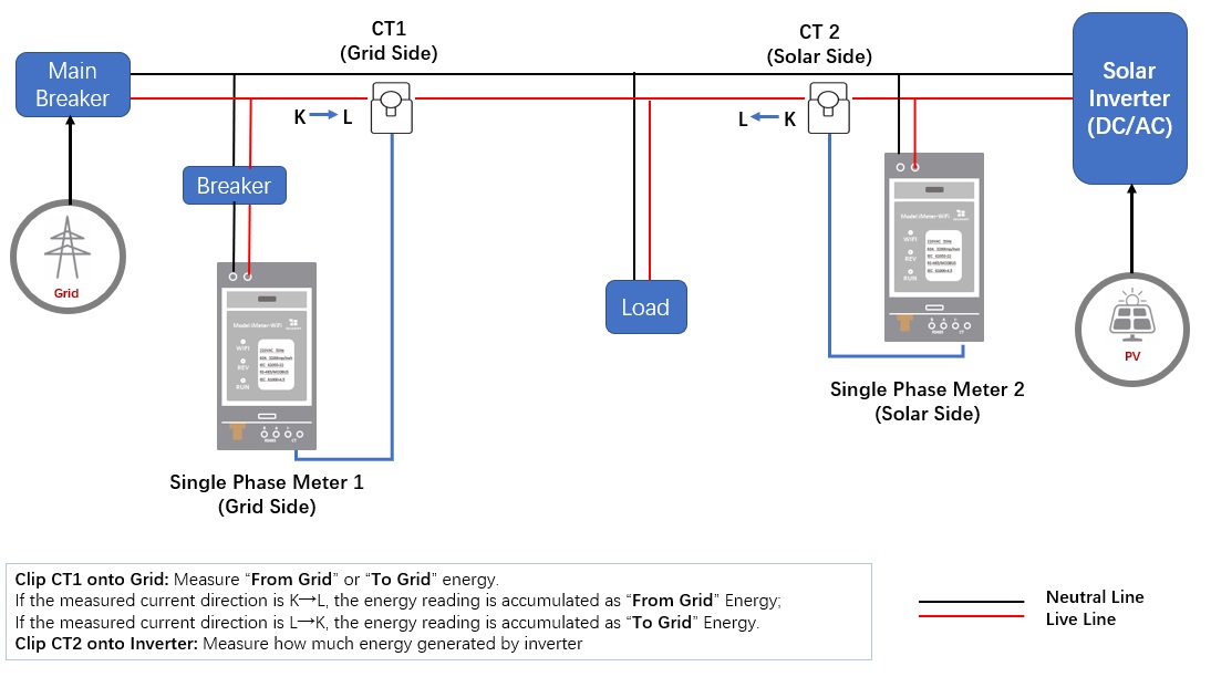
If you want to monitor a full home solar system in a single-phase installation, including grid and inverter at the same time, refer to the dedicated solar wiring guide:
Split-Phase Wiring
Applicable meters:
Split-phase systems are common in North America. They normally include:
- Two hot lines:
L1andL2 - One neutral wire
- 240V between
L1andL2 - 120V between each hot line and neutral
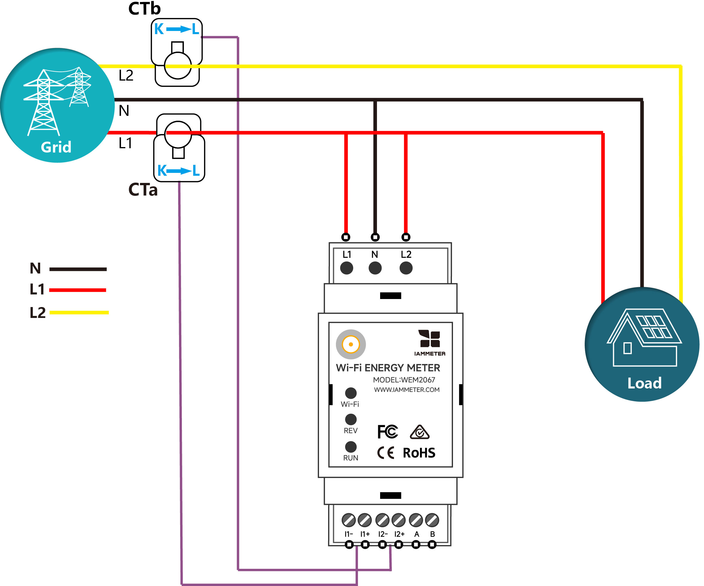
Option 1: Use WEM2067 for Split-Phase Grid Monitoring
WEM2067 is a practical option for split-phase systems because it provides two measurement channels and is well suited for residential monitoring.
Basic wiring rules:
- Use one channel for
L1 - Use one channel for
L2 - Make sure each voltage input matches the corresponding CT channel
This is a good choice when you want to monitor a split-phase grid or two split-phase branch circuits with a compact residential meter.
Option 2: Use a Three-Phase Meter in a Split-Phase System
If you want to monitor both the split-phase grid and the inverter at the same time, WEM2067 is no longer enough because it only has two measurement channels. In this case, you need to use a three-phase meter, such as:
IAMMETER provides a special parameter, CTCratio, on its three-phase meters. This makes it possible to use one three-phase meter to monitor both a split-phase grid and a split-phase inverter in the same system.
For WEM3050T, please note that Uc must be powered, otherwise the meter will not work properly.

For the detailed wiring method and CTCratio setting, refer to:
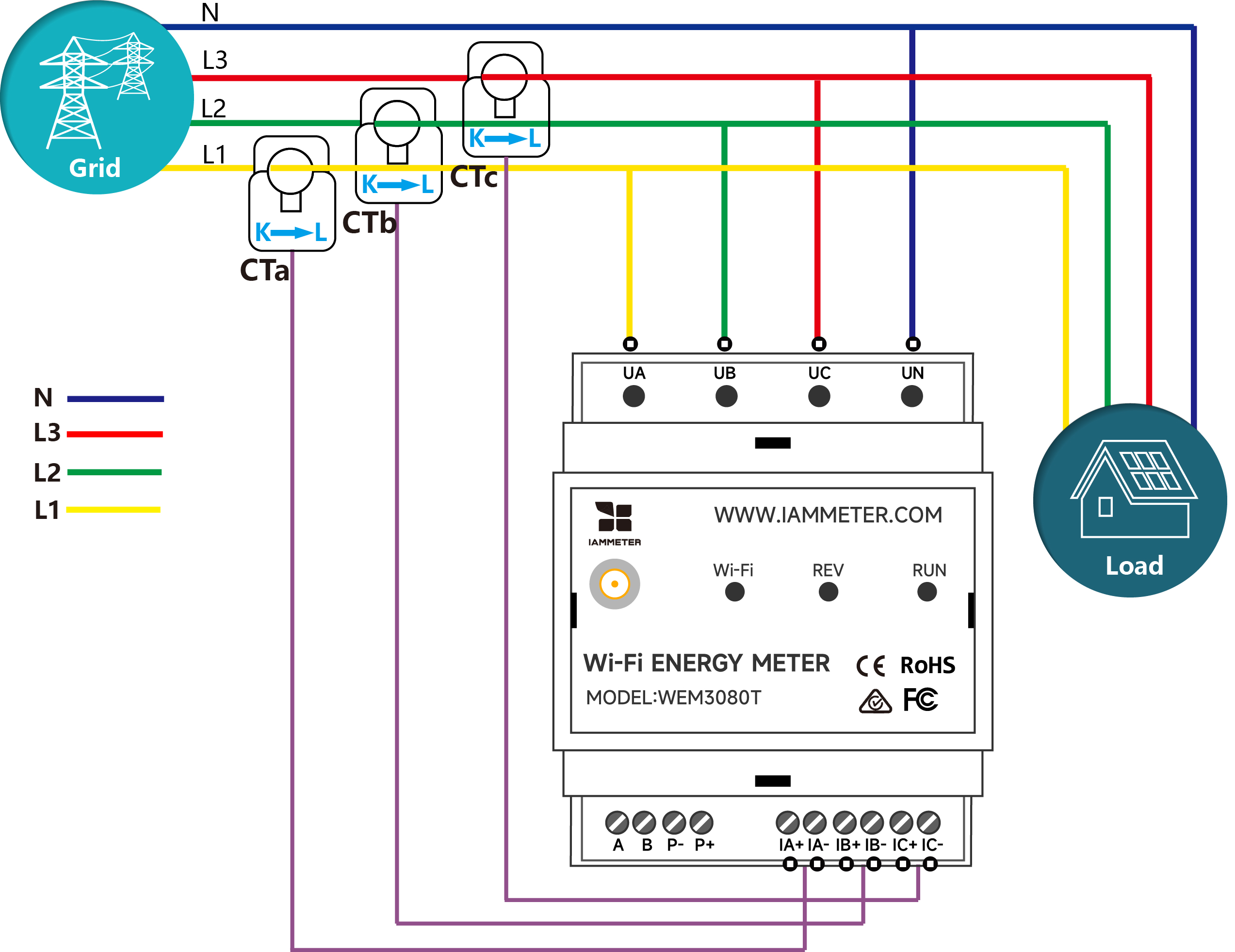
Three-Phase WYE Wiring
Applicable meters:
A three-phase WYE system normally has:
- Three phase lines:
L1,L2,L3 - One neutral wire
Basic wiring rules:
- Connect
L1,L2,L3, andNto the corresponding meter terminals. - Clamp
CTa,CTb, andCTcaroundL1,L2, andL3. - Make sure each CT matches its voltage phase.
- Point each CT arrow toward the load for standard consumption monitoring.
If your application is a three-phase solar PV system and you want to monitor both the grid side and the inverter side, refer to the dedicated solar wiring guide:
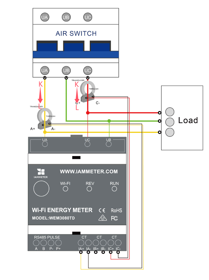
Three-Phase Delta Wiring
Applicable meter:
In a delta system:
- There is no neutral wire
- WEM3080TD is the dedicated IAMMETER model for this wiring type
Basic wiring rules:
Uaconnects to Line AUbconnects to Line B as the voltage referenceUcconnects to Line CCTameasures Line ACTcmeasures Line CCTbis not used
| Diagram | Description |
|---|---|
 |
Ua -> A, Ub -> B (reference), Uc -> C |
Note:
- In delta mode, Phase B power will show
0, which is normal.
Secondary CT Wiring with WEM3046TE
Applicable meter:
WEM3046TE is designed for secondary CT measurement. It is used when the meter does not clamp the main conductor directly, but instead measures the 5A secondary loop of an existing primary CT.
Typical use cases:
- Industrial monitoring
- Commercial projects
- Large current systems using external CTs
Basic wiring rules:
- Connect
Ua,Ub,Uc, andNto the corresponding voltage inputs. - Clamp
CTa,CTb, andCTcaround the secondary wires of the external CTs. - Keep CT direction consistent with the primary CT current direction.
- Set the correct CT ratio in software after installation.
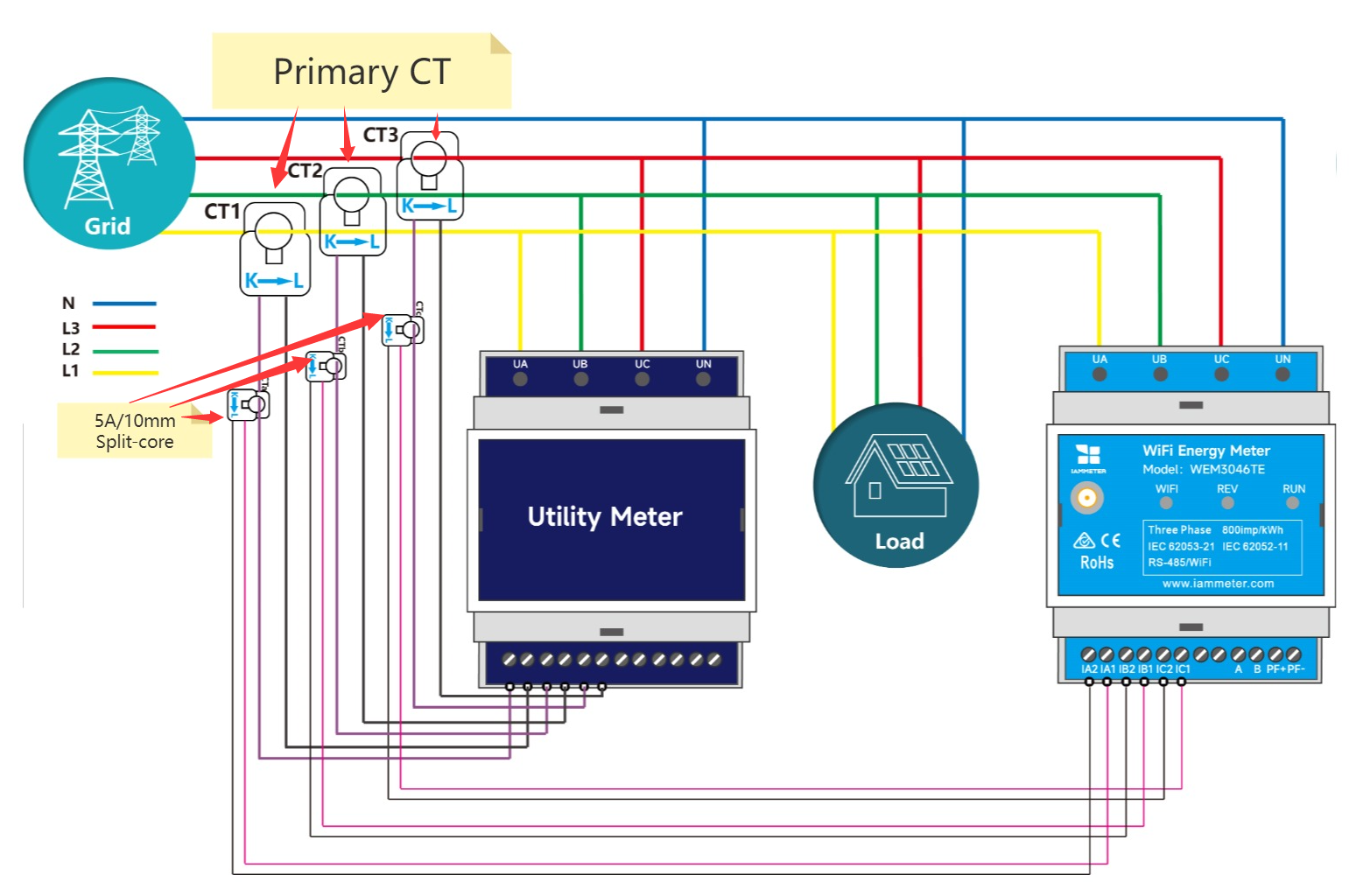
Example:
- If the primary CT ratio is
2500A : 5A, set the CT ratio to500.
Solar PV Wiring Examples
This guide focuses on system-type-based wiring selection. For solar PV examples, including:
- Single-phase grid + single-phase inverter
- Split-phase grid + inverter
- Three-phase grid + three-phase inverter
- Three-phase grid + single-phase inverter
refer to the dedicated solar wiring guide:
Common Wiring Mistakes
| Mistake | Description | Fix |
|---|---|---|
| CT direction reversed | Negative readings or reversed power flow | Reverse the CT direction |
| Phase mismatch | CT does not match its voltage input | Match CTa -> Ua, CTb -> Ub, CTc -> Uc |
| Neutral not connected in WYE system | Incorrect or unstable voltage readings | Connect neutral correctly |
| Loose terminal | Unstable readings or intermittent loss | Tighten all connections |
More details:
Additional Tips
- Label CTs and wires clearly during installation.
- Avoid routing CT cables close to strong magnetic interference sources.
- For long CT cable runs, use shielded twisted-pair wiring.
- After installation, compare phase readings and total power to verify the wiring result.
Support
- Website: https://www.iammeter.com
- Docs: https://www.iammeter.com/docs
- Email: support@devicebit.com


")
")